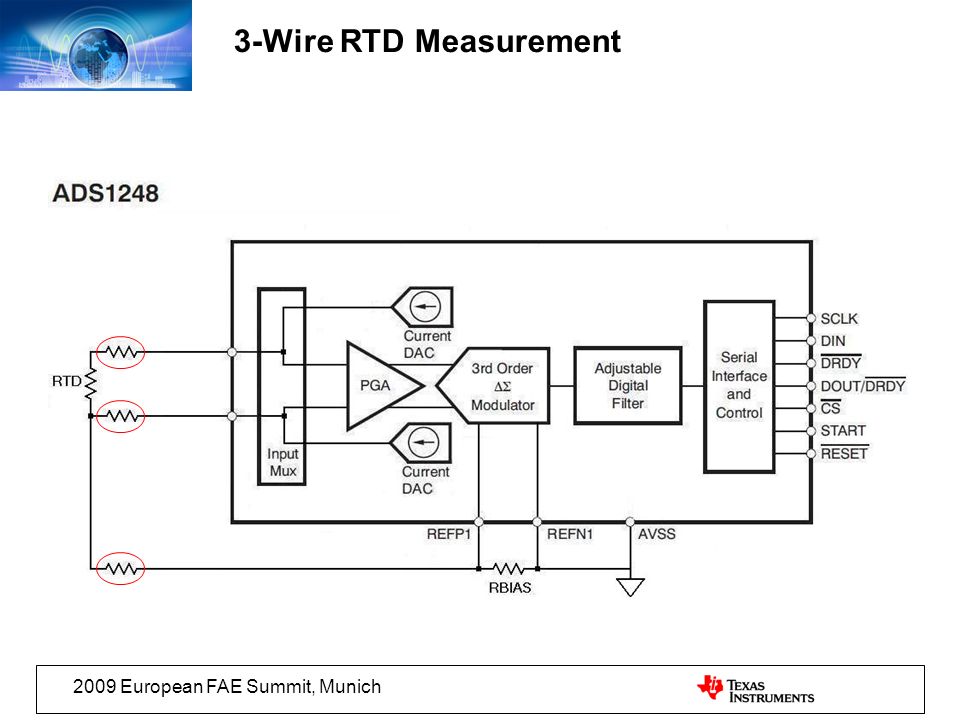
Sensors and to the rtd module according to the following diagram on the left. The following connection diagrams illustrate how to connect various rtd types to your daq device.
 4 Wire Rtd Connections Diagrams Ecourbano Server Info
 A1b1 a2b2 and c1c2 have the same wire color.

Rtd wiring diagram. L1 and l3 carry the measuring current while l2 acts only as a potential lead. Using this method the two leads to the sensor are on adjoining arms. 4 wire rtd signal connection connect each of the red leads on the positive side of the resistive element to the excitation positive and channel positive on the daq device.
No current flows through it while the bridge is in balancesince l1 and l3 are in separate arms of the bridgeresistance is canceled. Rtd wiring instruments from im 205 rev. F appendix 3 september 2009 rtd module and pt100 wiring module optional note.
This is the easiest wiring you can just use either terminal block slot on the sides for each wire. Assortment of rtd pt100 3 wire wiring diagram. Why use a 2 wire rtd.
Visit the post for more. In order to minimize the effects of the lead resistances a three wire configuration can be used. A wiring diagram is a simplified standard photographic representation of an electrical circuit.
Using 2 wire rtds provides fair temperature measurement when thereceiving device is connected directly to the sensor without the use of extension wire. In this circuit there are three leads coming from the rtd instead of two. Image is loading rtd pt100 temperature sensor probe cable 3 wires pt100 temp sensor wiring diagram diagrams 3 wire simple schema temperature rtd pt100 temperature sensor probe 3 wires cable thermocouple 58 572f 50 300c 1 2 npt thread.
This is the simplest and least expensive configuration but also the most limiting. 3 wire rtd wiring diagram awesome rtd sensor temperature ppt video. What is an rtd rtd types uses and more by jms southeast.
3 wire rtd wiring diagram. Collection of 3 wire rtd wiring diagram. There is a lead resistance in each arm of the bridge so that the resistance is cancelled out so long as the two lead resistances are accurately the same.
It shows the components of the circuit as streamlined shapes and also the power and also signal links between the gadgets. It reveals the parts of the circuit as simplified forms and also the power and also signal links between the devices. A wiring diagram is a streamlined standard photographic depiction of an electrical circuit.
Rtd pt100 3 wire wiring diagram gallery rtd sensors 2 3 4 wire rtd sensors resistance temperature detectors. Sor resistance temperature detector rtd proflow systems. Then either solder closed the jumpers next to the rtd terminal block or put little wires in the right and left terminal blocks to short them together.
3 wire rtd description.
 2 Wire Wiring Diagram Share Circuit Diagrams
  Six Wire Rtd Schematic Mcafeehelpsupports Com
  Rtd Transmitter Wiring Diagram Awesome Rtd Sensor 2 Wire Rtd 3 Wire
  Rtd Wiring Diagram Wiring Library
  3 Wire Rtd Wiring Wiring Diagram Bookmark
  3 Wire Rtd Wiring Diagram Vanphongchinhchu Com
  4 Wire Rtd Evolution Sensors And Controls
  Polarity 3 Wire Rtd Wiring Diagram Wiring Diagrams Home

0 comments